Friday, 27 March 2009

More on the frame

I mused yesterday that I might have two bikes welded together. This theory is based on the weld visible around the crossmembers and around the complete circumference of the main tube, and would also explain some anachronistic parts on the scoot.

There are of course other theories, and mulling it through overnight I now think the 'two bikes' theory is unlikely because of this:

1. If you're so bad at welding that you can't get the crossmembers on straight in either axis, how on earth would you manage to weld two frames together, dead straight?

2. There would be little incentive to do this kind of thing in India. As Dave Williams, author of The Indian Lambretta Guide says: "I cannot imagine a scenario in India (unlike here possibly) where two frames would need to be welded together....Remember that Lambys have no significant value in India so there would be no incentive..." This is a fair point.

3. It's more likely that the frame was showing signs of stress, perhaps even a fracture, that necessitated a stengthening plate top and bottom and a cirumferential weld.

Anyway, back to those crossmembers. Need to find a welder!

Thursday, 26 March 2009

Frame problems

I knew things weren't quite straight on this scoot, but I thought this was limited to a sagging crossmember that might be bent back into place. Having removed the forks and now the legshields it has all become a little clearer:


They are off by a country mile, and I can't believe the legshields actually fitted. And they haven't bent, they've been welded like that:


There's also evidence that this might be two frames welded together. There are strengthening plates on the top and bottom of the tube (which apparently isn't that unusual), but there is a weld around the complete circumference of the main tube. Two bikes welded together would explain a lot - the early parts on a '77 scoot.

Whatever has happened, I know three things:

1. It's a mess, and I'll at least have to chop off the crossmembers and get new ones welded on properly. At the same time I'll get an expert welder's opinion on the main tube.
2. The frame is strong (and safe), as the bike has clearly been very heavily used over a long period on probably some shocking roads.
3. My key measurement from toolbox to steering cone is correct, and visually the main tube looks straight, but I'd still like to get this checked properly.

Wednesday, 25 March 2009

Forks out

With the proper fork nut spanners, removing the forks was easy. The steering felt really good on this bike and I actually considered not removing the forks. But I'm glad I did, look at the condition of the bearings that came out:

Headset / handlebar

Removing the headset is pretty straightforward, and the first step is to remove the headlamp. On an old bike, especially from India, you will probably find a complete mess:


One of the more difficult things was removing the old grips from the handlebars. I resorted to using a sturdy screwdriver and a hammer to chisel my way through, as WD40 simply didn't work. This pic shows the grip removed and my new black dog-leg lever fitted to the gear changer:


I went for this lever as it's a good match for my new hydraulic front brake lever, which you can see fitted here on my stripped down (but not cleaned!) headset:


Fitting this new hydraulic brake lever required some light filing on the tapered part of the handlebar. When re-fitting the throttle shaft I had some trouble getting it all to fit. I couldn't get the hole in the throttle wheel to line up with the hole on the end of the shaft. This must be because the new polished alloy switch housing for the new hydraulic lever is a couple of mm too long. The solution? File a couple of mm off the paddle that locates the other end of the shaft to move it all along a little:

Tuesday, 24 March 2009

Piston, cylinder and head fitting

I checked the gap on my piston rings prior to fitting and found they were a little too tight. Some light filing increased the gap to over 0.2mm, the minimum recommended. The brown rings seen on the walls of the cylinder in this photo are build-ups of oil where the rings had been kept in storage:


The easiest way to get it all together is to place the piston with rings into the cylinder while on your workbench. Make sure the arrow on the piston head points towards the exhaust port, and make sure you've lightly oiled your cylinder and beneath your rings with 2-stroke oil. Tease the cylinder far in enough to retain the rings.

Fit your bottom gasket and long cylinder studs. Grease the gasket and cylinder studs to help fitting and future removal, then offer the cylinder/piston assembly up to the studs and slide down until the piston reaches the conrod. Now you can fit the circlips, gudgeon pin, and bearing (lightly oiled) so that the piston is attached. Then slide the cylinder all the way home.


I used a high-temp gasket sealant for the head gasket. Make sure you only use a little as it'll ooze out the side when you bolt it all down!

Here's a top tip, before you fit the head screw in a spark plug all the way and wipe away any burr or deposits - better this ends up on a rag than in your cylinder.

Tighten the head bolts in a diagonal pattern to about 2kg-m.

Monday, 23 March 2009

Stator plate, flywheel and timing

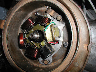
Here's the new stator plate fitted:


To get this sitting in exactly the right position I used a timing disc rather than a dial gauge:

1. Place the flywheel onto the shaft (with the woodruff key fitted).
2. Rotate to TDC (Top Dead Centre) - the point where the piston is at the top of its travel.
3. Mark the magneto housing where the arrow is pointing.
4. Remove the flywheel and place the timing disc on the shaft. Measure the angle anti-clockwise where you want your timing to be (see manuals for advice for your engine, typically 19-23 degrees). Mark this point on the housing.
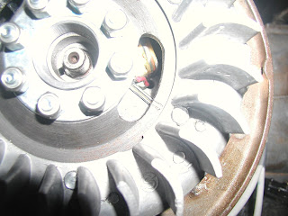
5. Put the flywheel back on, point the arrow to your timing mark and look at the two lines on the edge of the window on the flywheel. These lines should match with the two lines on the black ignition pick up. If they don't, then you make adjustments now to the stator plate position to get them to match:


I'll make final adjustments when the engine is fitted and running, by using a strobe to ensure that these do match at the firing point.

Friday, 20 March 2009

Kick start shaft and lever

Fitting the shaft and its spring was pretty tricky. I started with the spring the wrong way first, and then realised the kinked end needs to go in the shaft. Fit the shaft fully (with shim, circlip and lever) prior to tackling the shaft guide, as then you can hold the pedal in a vice and rotate the casing to make installation of the guide easy.

I bought the shaft and the long bolt from Scooter Restorations, but the bolt they supplied wasn't long enough, even after squeezing the lever tight on to the shaft:


and so I resorted to my collection of stainless bolts inherited from my grandfather, who was a metalworker and coachbuilder. Here you can see one of my many pots of nuts and bolts, and a suitable one I found fitted to the shaft:


And here's the kick shaft and clutch cam installed. The kick shaft here is prior to some adjustment:

Tuesday, 17 March 2009

Rear brakes

This all went together predictably. I made sure to keep my greasy fingers off the shoes, and I degreased the hub before fitting.

Thursday, 12 March 2009

Clutch / cush drive / chain install

The photo below shows the crownwheel, clutch spider, drive sprocket, dog, spring and cap installed. There are a few things wrong here; if you fit them like this you won't be able to fit the chain, and also the top chain guide is bolted above the bottom and it should be the other way!


So I had to undo the crownwheel and spider to fit the chain:


After stacking up the steel and cork discs of the clutch onto the clutch flange on top of the springs, I compressed it all with my cheap clutch compression tool. I used a socket to spread the load as it was pressing one side further down than the other:


When partially compressed use a screwdriver to nudge the springs into the correct seated position. When fully compressed you can fit the large circlip to hold it all in. Make sure that the end is covered by one of the lips of the spider.


I undid the chain guides after this and placed them correctly (the upper one beneath the lower one). Correct adjustment of the upper guide should give you around 10mm of movement in the chain between the guide and the front sprocket.

Monday, 9 March 2009

Mag / Flywheel bearing installation

Here's the bits that go into the magneto housing. An outer oil seal, a cup to retain the outer seal, the bearing, a larger inner oil seal, and a big meaty circlip to keep everything in.

My photo doesn't show them in any order:


There were no problems slotting all this into place - again I used the old bearing as a help, but the big circlip was a problem for my puny circlip pliers. Here it is all greased up and ready:


I used nyloc stainless nuts to fit the mag housing, and grease on the gasket for a tight seal but to aid future removal. When fitted I checked there was no rubbing against the crack using a feeler gauge: